As you already know, PID controllers include three adjustable parameters: the controller gain; the integral time constant (sometimes called the reset time); and the derivative time constant. Controller tuning involves setting these three parameters at values which suit the process to be controlled. The tuning process can be thought of consisting of three stages: specification of the problem; choice of the control modes required; selection of appropriate tuning values.
PID tuning is sometimes regarded as a dark art, and is often carried out in a very cursory fashion. A survey of process plants in the USA found that between 65% and 80% of the PID loops were badly tuned and were seriously affecting the performance and profitability of the process. In most cases, however, tuning a PID controller isn't really that difficult and just takes a bit of patience and experience (the exception is in strongly interacting multi-loop systems, which are discussed later in the course).
Most modern PID controllers now have an autotuning feature which, in theory, will set the controllers parameters automatically after a short experimentation period. While these autotuners work in some situations they don't work well in others, and shouldn't lead you to think that you'll never have to tune a controller once you finish this course!
Before you dash out to the plant and start twiddling with a controller, you need to make sure that you clearly understand what the control problem is. Some of the questions you need to have answered are:
Although a PID controller has proportional, integral and derivative control modes it is relatively unusual for all three to be used. PI control is the most common combination in the process industries, followed by P and then by PID control. Other combinations such as I and PD control are only rarely encountered.
Luyben has proposed the following 'rules of thumb' for the selection of control modes for common types of loop:
Most flow loops involve simply a flow measuring device and a control valve - the process dynamics are essentially the dynamics of the control valve. The loops are therefore very fast compared to most other process loops. They are also usually quite noisy (flow measurement suffers more from noise than any other process measurement).
'PI controllers are used on most flow loops. A wide proportional band setting (PB=150) or low gain (0.67) is used to reduce the effect of the noisy flow signal due to flow turbulence. A low value of integral or reset time (Ti = 0.1 minutes) is used to get fast, snappy setpoint tracking.'
'Most liquid levels represent material inventory used as surge capacity. In these cases it is relatively unimportant where the level is, as long as it is between some maximum and minimum values. Therefore, proportional controllers are often used on level loops to give smooth changes in flow rates to downstream units.'
'If PI level controllers are used, the integral action forces the level back to its setpoint. In fact, if the level controller is doing a "perfect" job, the level is held right at its setpoint. This means that any change in the flowrate into the surge tank will immediately change the flow rate out of the tank. This defeats the purpose of buffering. We might as well not even use a tank; just run the inlet pipe right into the outlet pipe!'
A simulation comparing the surge prevention capabilities of P and PI level control is here.
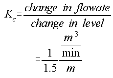
Tuning of the proportional controller can be achieved by specifying the maximum change in level allowable for a given disturbance flowrate change. For example, lets say that the level could change by up to 1.5 m when the disturbance flow changed by 1 cubic meter/min. The controller gain would then be:

note that the gain is dimensioned - it would need to be converted to a dimensionless gain to be used in most commercial controllers.
'Temperature control loops are usually moderately slow because of the sensor lags and
the process heat transfer lags. PID controllers are often used. Proportional gains are
fairly high, depending on temperature transmitter spans and control valve sizes. The reset
time is usually of the same order as the process time constant; i.e. the faster the
process, the smaller ![]() i can be
set. Derivative action is set something like one-fourth of the process time constant,
depending on the noise in the transmitter signal.
i can be
set. Derivative action is set something like one-fourth of the process time constant,
depending on the noise in the transmitter signal.
Although there are a number of semi-structured methods of obtaining controller tuning values (e.g. Cohen-Coon, Ziegler-Nichols), they only ever give values which are approximately in the right range and extra, manual, tuning is usually required. They are rarely used in real controller tuning. Most tuning is usually done by trial and error. One method of approaching trial and error tuning is given below, but you shouldn't regard this as Gospel - with experience you'll develop your own method.